Ordinate
Add ordinate dimensions to the drawing showing the X or Y distance from the axes (specified by the origin).
Icon |
Command |
Shortcut Key |
Toolbar |
|
DIMORDINATE |
|
Dimensions |
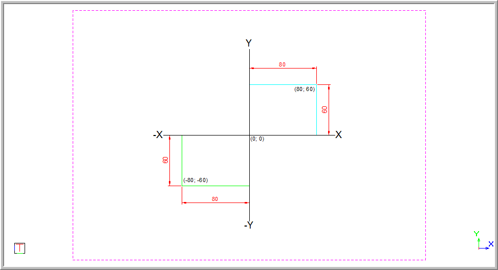
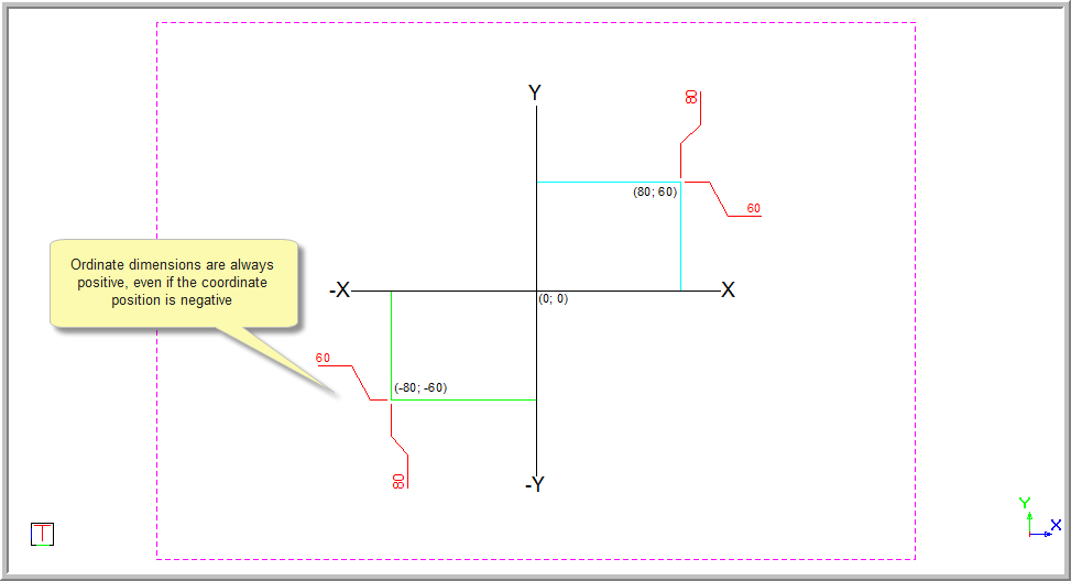
Ordinate dimensions show the distance of a point from the X and Y axes.
This function allows you to add ordinate dimensions to show the position of a point relative to the distance from the axes (specified by the origin), by indicating the point to be dimensioned and then indicating the position for the dimension text. The Horizontal datum option is used to specify ordinates on the X-axis, and the Vertical datum option is used to specify ordinates on the Y-axis.
Ordinate dimensions only work in Cartesian drawings, and are always given in the positive even though the coordinates can be negative.
Surveyor drawings will always use the absolute ordinate value i.e. relative to the drawing origin.
The ordinates can either be given according to the World Coordinate System, or from a user defined origin if you have graphically set the Drawing Plane Origin.
The user defined origin option is only applied when the DP Local is selected and has been activated on the Status Bar.

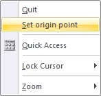
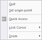
You can also change the origin point by right-clicking and selecting the Set origin point option from the popup menu.
Ordinate dimensions can be:
Free - Each dimension is drawn individually.
Chained - Successive dimensions follow on the previous dimension.
 Dimensions use
the current line style.
Dimensions use
the current line style.
Procedure
In this example, you will see the horizontal and vertical dimensions.
- You are prompted to:

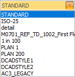
- The dimension style can be selected from the dropdown list. Alternatively,
click
 to change the dimension
style.
to change the dimension
style.
Specify a horizontal or vertical datum.

The Point snap mode is active.
Select the Text override checkbox if you want to be able to edit the text.
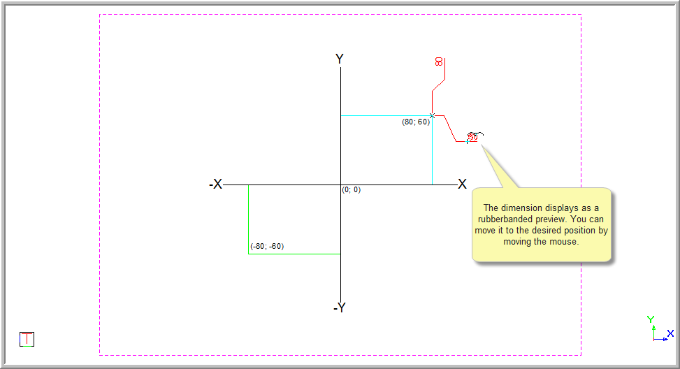
Horizontal Datum Style
Select the Horizontal datum style.
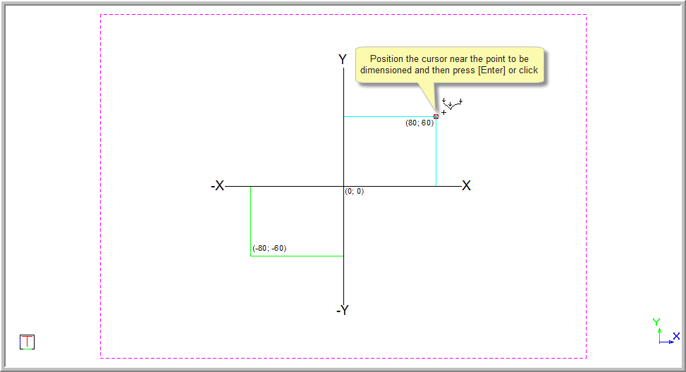
- Position the cursor at the point to dimension and then press [Enter] or click. The dimension displays.
- You are prompted to:

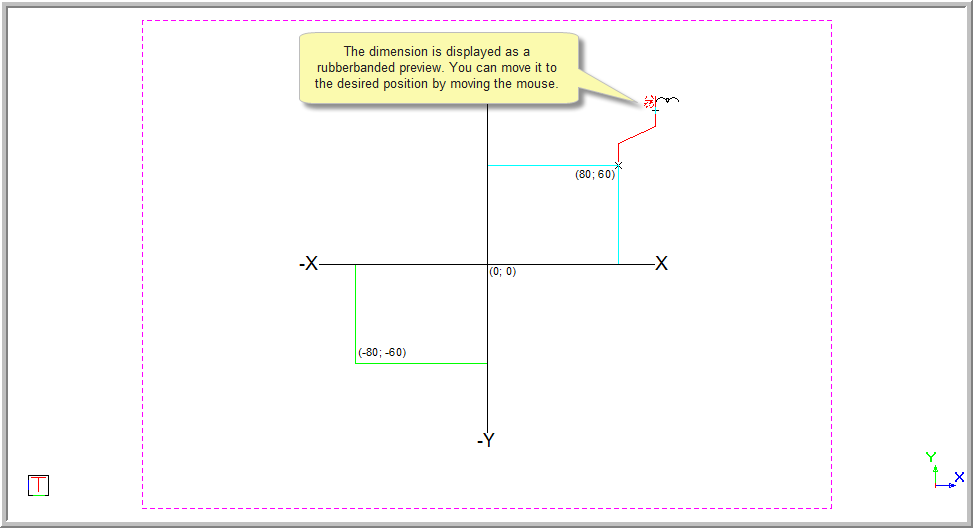
A rubberbanded preview of the dimension is drawn and you can move the mouse to indicate the dimension offset. Press [Enter] or click in the desired position.
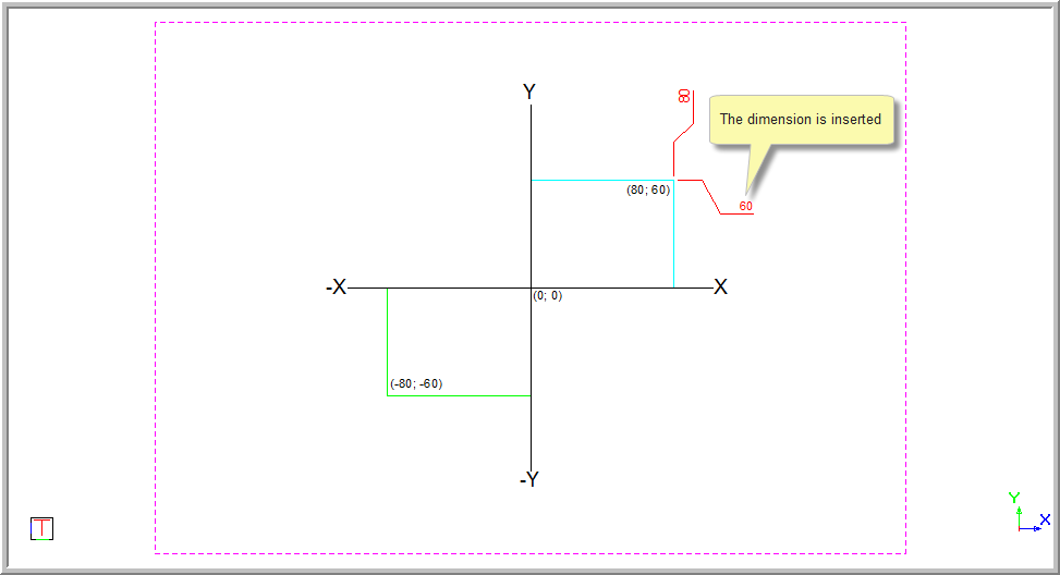
If you have selected the Text override option, you are prompted to override text . Type over the text and then press [Enter] or click Enter to insert the dimension.
If the Text override was not selected the original measurement will be inserted.
- You are prompted to:

- You can continue to add dimensions as the function repeats.
Vertical Datum Style
- Select the Vertical datum style and indicate the point to dimension by pressing [Enter] or clicking.
- You are prompted to:

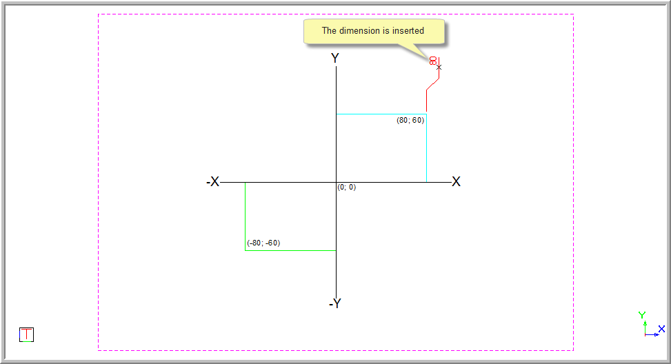
- The rubberbanded preview is shown and you can move the mouse to indicate the dimension offset. Press [Enter] or click in the position to insert the dimension.
Remember, if you have the Text override selected you can now change the text value.
Press [Enter] or click in the position to insert the dimension. The dimension is inserted.
Ordinate dimensions are always shown as positive measurements even if the coordinate position they are indicating is negative.
- Right-click and select Cancel to discontinue with the current alignment and continue dimensioning using a new starting point. Alternatively, select Quit or press [Esc] to end the function.
Setting the Ordinate Dimension Origin After the Dimension Has Been Drawn
To set the ordinate dimension after the dimension has been drawn:
Select the ordinate dimension and press [F4] to show the Property Bar.
In the Ordinate dim’s property list, scroll down to the bottom and click Edit origin.
You are prompted to indicate a new origin point for the ordinate dimension.
- The ordinate dimension value updates to be relative to the new origin.