Polygon Mesh
Draw a grid of points that are joined by 3D faces.
|
Icon |
Command |
Shortcut Key |
Toolbar |
|
|
POLYMESH |
|
Drawing |
This function allows you to draw a polygon mesh by specifying the size of the mesh in the M and N directions. Thereafter, indicate the four points of the mesh to create a planar mesh.
 To create smoother surfaces, use the vertices as control points for a Bezier surface by selecting a smoothing type from the Properties Bar.
Procedure
- You are prompted to:

This specifies how many vertices there will be in the direction of the fourth vertex of the quadrilateral from the first. This is one more than the number of faces in this direction. Enter a value and press [Enter] or click Enter  .
.
- You are prompted to:

This specifies how many vertices there will be in the direction of the second vertex of the quadrilateral from the first. This is one more than the number of faces in this direction. Enter a value and press [Enter] or click Enter .
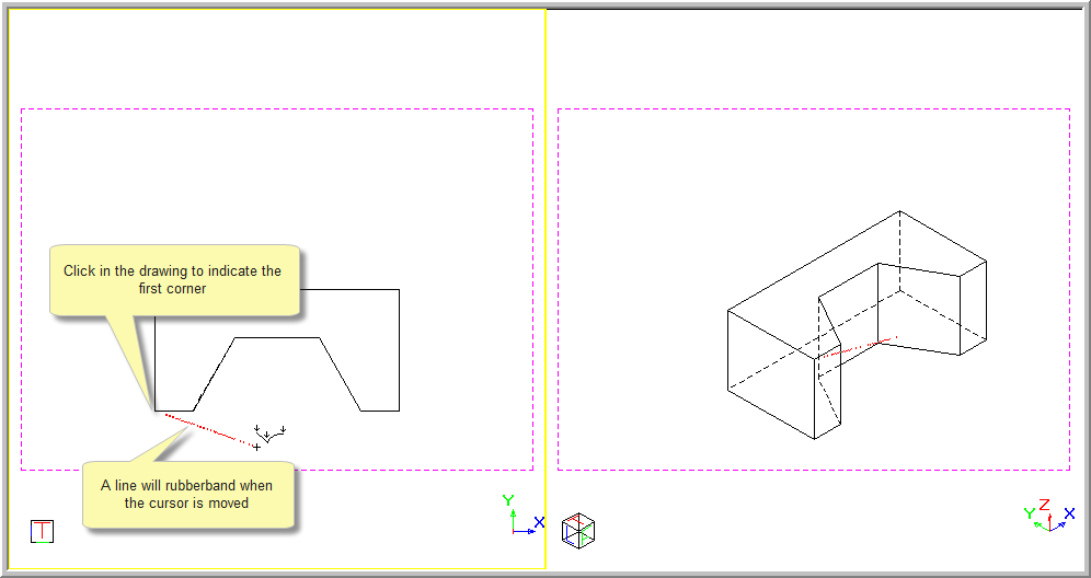
- You are prompted to:
Indicate first corner of the 3D mesh
- Click in the drawing to indicate the first point of the face. A line rubberbands when the mouse is moved.
- You are prompted to:
Indicate next corner of the 3D mesh
-
Move the cursor to the position of the second point and click to indicate the point.
- You are prompted to:
Indicate next corner of the 3D mesh
- A meshed triangle is visible when the cursor is moved. The number of "N" vertices is shown.
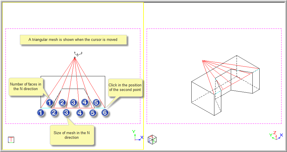
-
Move the cursor to the position of the third point and click to indicate the point.
- You are prompted to:
Indicate next point of the 3D mesh
- A meshed quad is visible when the cursor is moved. The number of "M" vertices is shown.
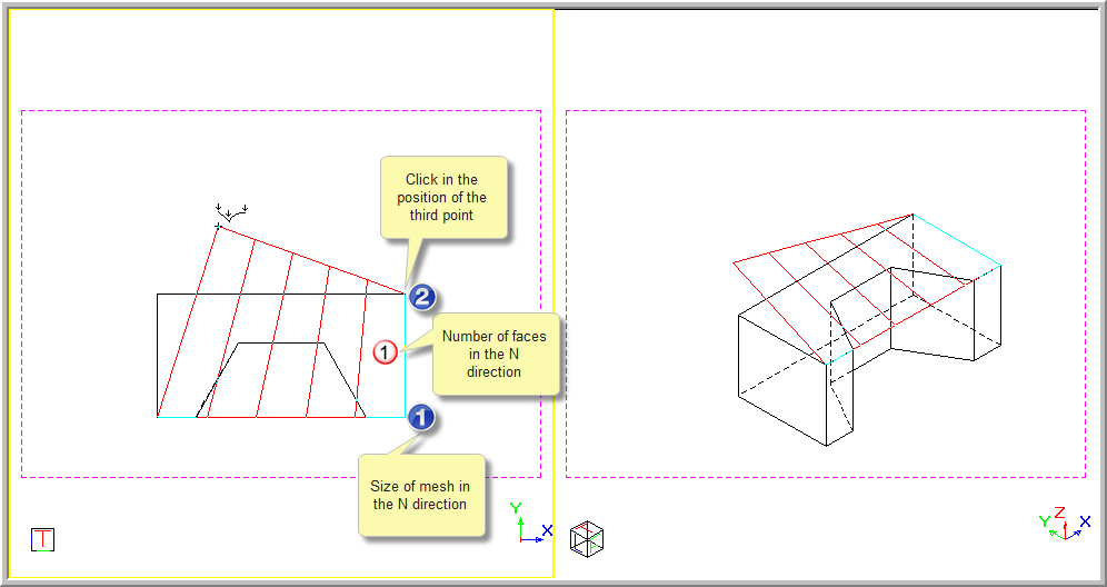
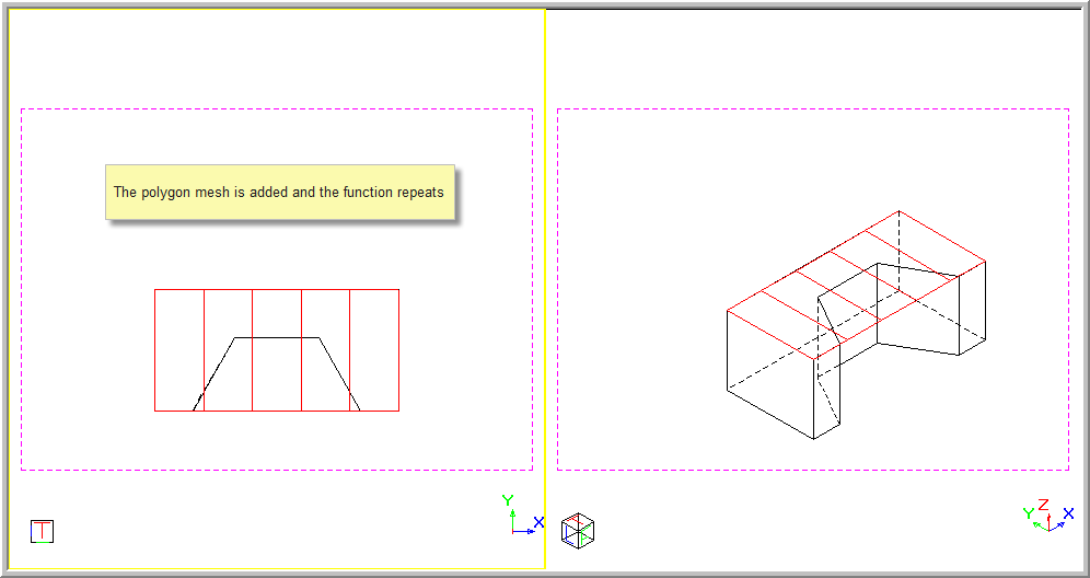
- Move the cursor to the position of the final point and click to indicate the point. The Polygon Mesh is added to the drawing and the function repeats.
- Right-click and select Quit to end the function. Alternatively, press [Esc].
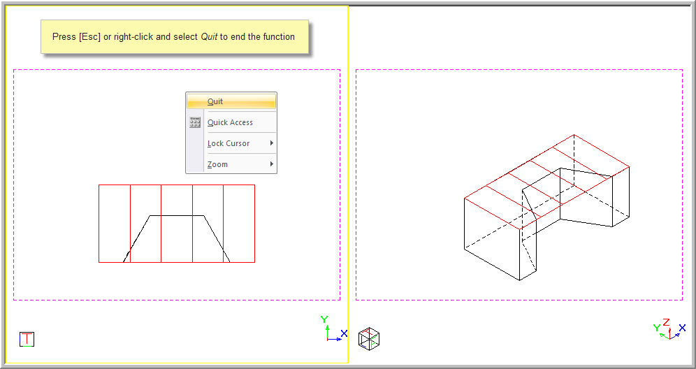
Note that you can right-click on the drawing and select Quit to end the drawing function at any stage; or select Cancel to end the current drawing but continue with the function.
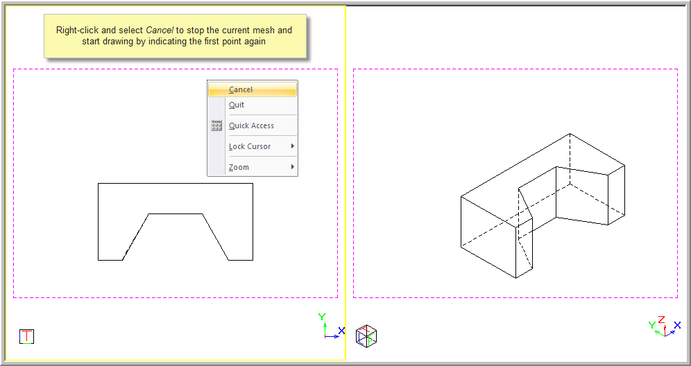
If you select Cancel, you will be able to start entering the points again.
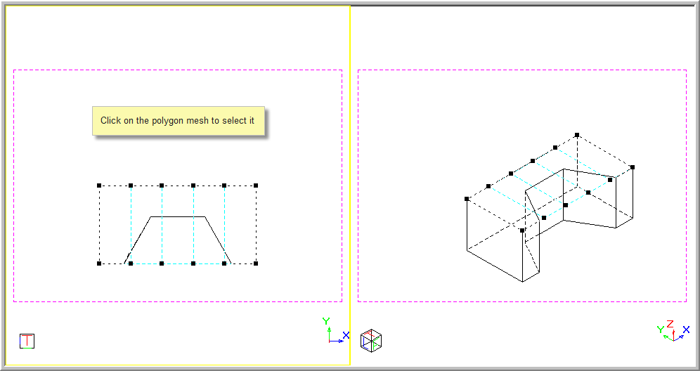
- You can now select the polygon mesh by clicking on it.
-
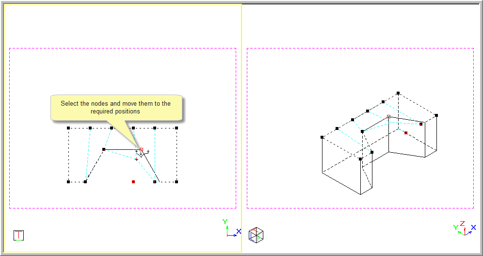
You can now select the nodes and move them as required.
-
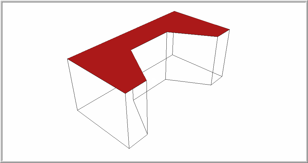
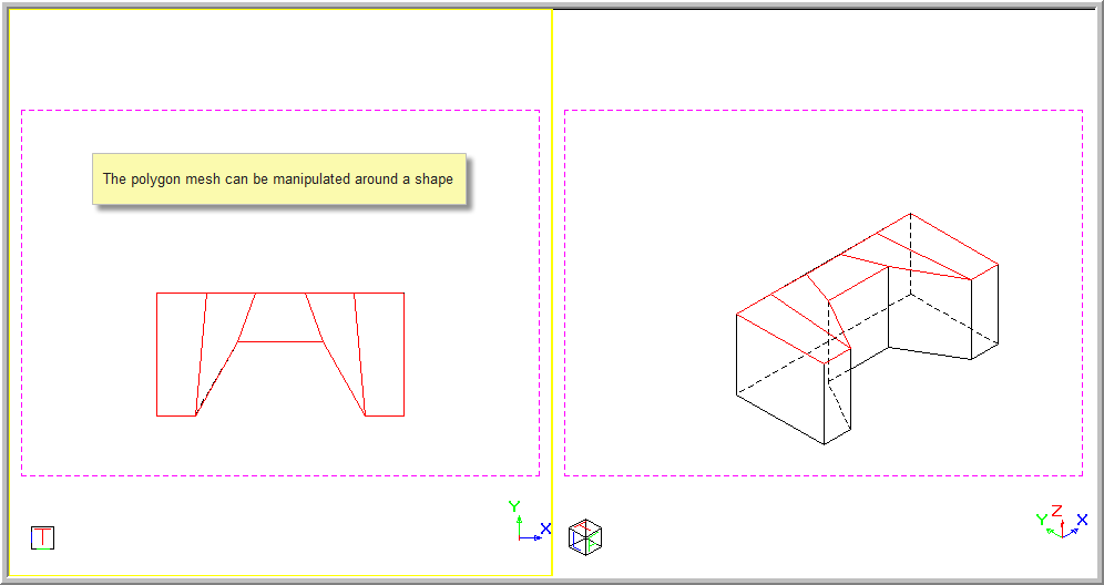
The polygon mesh can be manipulated around a shape to be filled.
-
The polygon mesh can be seen as a solid face in a rendered view.