Export to IFC
Export all or part of a project’s geometry as one or more IFC files.
|
Icon |
Command |
Shortcut Key |
Toolbar |
|
|
EXPORTIFC |
|
|
This function allows you to export all the geometric data in the project as one or more IFC files, which are used as part of a BIM system.
The IFC files contain 3D watertight “solid” model geometry representations of the project’s objects, such as Water pipes and nodes. Terrain surfaces and road surfaces are also exported as surface mesh objects.
Various IFC properties and quantities are attached to the 3D objects. In addition, a “persistent GUID” is attached to each exported object so that it can be uniquely identified if the IFC file is merged into a BIM project that has older versions of the same IFC objects.
You can choose which Civil Designer addons/modules you would like to export, and whether you would like to export them to one file, or separate files.
You can also choose whether to include BIM/QS “classification codes” for each object in the IFC file, which aids in the generation of quantities in a suitable BIM application. The IFC catalogues available are “Uniclass 2015”, “Uniformat 2” and “ASAQS SMM”.
Procedure
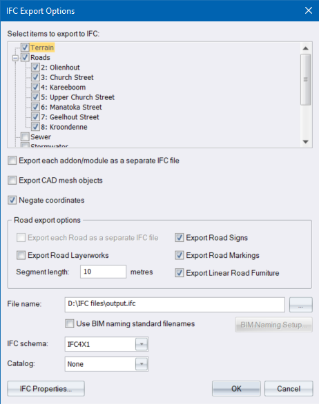
- In CAD mode, select File ► Import/Export ► Export to IFC file to display the IFC Export Options dialog.
-
Select which modules you want to export by selecting the appropriate checkboxes.
-
For Roads, you can also select which roads you want to export. Note that no roads will be exported if the main Roads checkbox is not selected.
-
You can right-click the Roads checkbox to open the popup context menu, which allows you to select or deselect all the roads.
-
-
Use the Export each module as a separate IFC file checkbox to select whether to export each module to their own IFC file, or all modules to one IFC file.
-
For Southern Hemisphere drawings, the Negate coordinates checkbox will be enabled. This may be necessary when the exported IFC files will be used in a BIM project, which contains geometry files from other design packages.
-
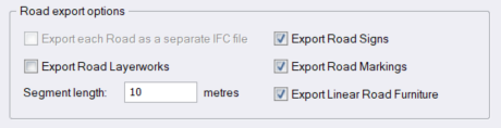
There are various road-specific export options:
-
-
Use the Export each Road as a separate IFC file checkbox to select whether to export each Road to its own IFC file, or all Roads to one IFC file.
-
Road layerworks geometry will be exported if you select the Export Road Layerworks checkbox.
-
If you specify a non-zero segment length, the Roads will be split up into chunks (separate IFC geometry objects) of the specified length.
-
You can also enable and disable the export of road sign objects, road marking objects and linear road furniture objects by using the relevant checkboxes in the road-specific export options.
-
-
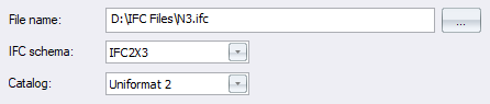
In the File name input box, enter a path and filename for the exported IFC file or click Browse… to select a folder and filename for the exported IFC file.
-
-
If you have selected to export each module as a separate IFC file, the module name will be appended to the file name you select e.g. if you enter a filename "N3 Project.ifc”, the Terrain will be exported as “N3 Project_Terrain.ifc”.
-
If you have selected to export each Road as a separate IFC file, the road name will be appended to the file name you select.
-
-
Select an IFC schema for the IFC files(s) that will be exported. Note that the schema you select must match one of those supported by whichever BIM system the exported IFC file will be used in.
-
If you want to include IFC "classification codes" for the objects exported to the IFC file, select an IFC catalog from the Catalog dropdown. Select None if you do not want to include the classification codes in the IFC file.
-
Click OK to start the export.
-
The IFC file(s) will be created for the modules you selected. For a large project, this may take some time. The resulting IFC files can be viewed in an IFC Viewer application and/or imported into a BIM system.
Configuring IFC Properties
IFC Properties are attached to each Civil Designer entity/object that is exported to the IFC file.
These IFC object properties are visible in an IFC viewer application or BIM viewer application, under the property category "PSet_CivDesCommon".
-
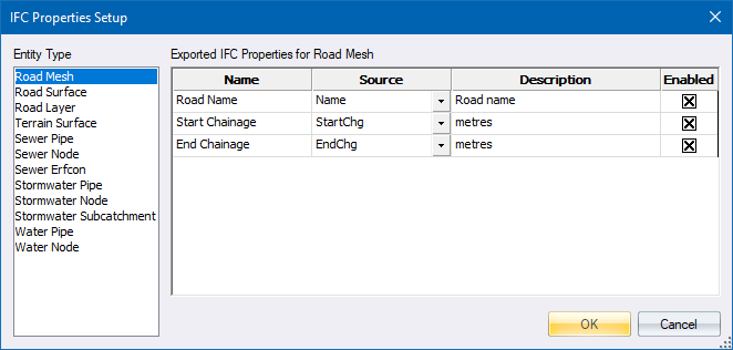
In the IFC Export Options dialog, click IFC Properties to open the IFC Properties Setup dialog.
-
Clicking on the list of Civil Designer entity (object) types in the left panel will display the IFC properties available for that entity type in the grid on the right.
-
These IFC properties are stored in the drawing’s dictionary i.e. they are saved with the drawing.
-
A default set of IFC properties for the current drawing is generated the first time you run the IFC Export function in that drawing.
-
You can edit the Name and Description of any property, and select whether it is exported to the IFC output file by selecting/unselecting the check box in the Enabled column.
-
The Name column allows you to specify the “display name” of the property as it appears in a BIM viewer application.
-
The Source column allows you to choose one of several entity properties to use as the "Value” for this IFC property in the IFC output.
- You can add your own “custom” properties by right-clicking on the grid and selecting Add from the context menu. In the image above, Completed Length has been manually added to the default properties:
-
Usually your custom property would have Source set to <empty>, and the property value in the IFC output will be blank/empty.
-
Note, if you set the Source to anything used by another property in the grid this property will overwrite the other property when exiting the IFC Properties Setup dialog using the OK button. This is because no two properties for a specific entity type can have the same Source.
-
Click OK to save your changes and exit this dialog; or Cancel to exit without saving changes.