Project Settings
Specify project settings.
|
Icon |
Command |
Shortcut Key |
Toolbar |
|
|
PROJECTSETTINGS |
|
|
This function allows you specify the project settings, including the design module data files and projection.
The project settings allow you to associate design files with the drawing. To create a new project, the first step is to open a new or existing drawing file.
Procedure
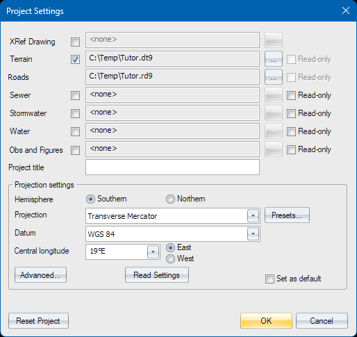
The Project Settings display.
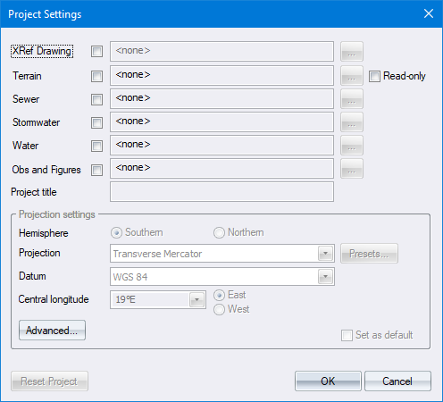
XRef Drawing
Select a drawing to be displayed as a backdrop (XRef) to the design. If the drawing has been changed, it automatically updates every time the project is opened.
Terrain File
To add a terrain file to the project:
- Select the Terrain checkbox.
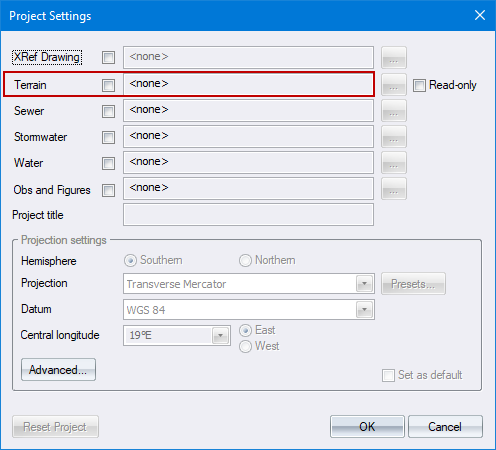
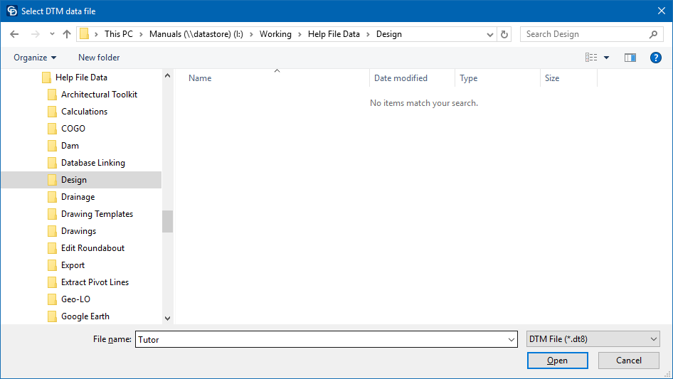
- The file browser displays. Select an existing terrain file or create a new terrain file.
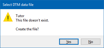
If you are creating a new DTM file, the following window displays. Click Yes to create the DTM file.
If you are adding an existing DTM file, you may not change the locale settings as the projection settings have already been applied to data files. The Project Settings dialog now displays the attached terrain file.
- In a similar manner you may create or add other design module files.
Projection Settings
You need to configure various settings that determine the manner in which the stored coordinates are projected onto the display surface (the Design Centre window). The settings can be made manually, via presets, or by reading them from a .PRJ file.
1. Manual Settings
a. Select either the Southern Hemisphere or Northern Hemisphere options to set the hemisphere in which the data is located.
b. Select the mapping projection to be used. Four projections are available, namely:
-
-
Local
-
Transverse Mercator
-
UTM (Universal Transverse Mercator)
-
New Zealand Transverse Mercator
-
Selecting Local causes Civil Designer to treat the Terrain and Road database coordinates with no projection.
c. Select the datum on which the data is to be based. This determines the ellipsoid on which the projection is based, and therefore the constants used for the mapping projection.
d. Enter the central longitude of the panel in which the data falls. Also select whether this longitude is East or West of 0° longitude (Greenwich).
e. Optionally, press Advanced for the Advanced project settings.
2. Preset Settings
The Presets button provides an alternative to manually specifying the traditional projection settings. In the Project Presets dialog, you can choose from various preset options that include all the needed projection settings without you knowing the details of them. When you select an option, the Project Settings dialog shows the chosen preset system option instead of the traditional settings.
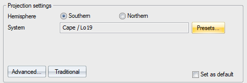
You can click Traditional to revert to the original settings.
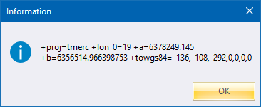
If you click Advanced with a preset chosen, it displays the technical data regarding the system for information purposes only.
3. Read Settings
a. Press Read Settings to choose an Esri .PRJ projection file to setup the projection settings with. This file is occasionally available from data providers, and is typically associated with Shapefiles or GeoTiffs. The file is ASCII format and starts with text PROJCS. Otherwise, it is not an applicable projection file.
b. You’re asked to choose the file, which is typically all that is required. Certain PRJ files have no hemisphere information, and then you will be further asked to choose North or South hemisphere.
Advanced Locale Settings
- Click Advanced in the Project Settings.
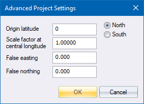
Origin Latitude
Enter the latitude on which the 0 value of the vertical ordinates of the coordinate system falls, and also select whether this latitude is North or South of 0° latitude (the Equator). This is normally set to 0° (origin at the equator where North or South are immaterial) but could be different for some projections.
Scale Factor at Prime Longitude
Enter the factor by which coordinates are adjusted in order to fit the projection. This is normally set to 1.0, except if you are using UTM or New Zealand TM coordinates (see Remarks below).
False Easting and False Northing
Enter the values to be subtracted/added to the LO coordinates during projection conversion. These are normally set to 0, except if you are using UTM or New Zealand TM coordinates (see Remarks below).
 Do not use the False Easting and False Northing settings to apply some constant to the data coordinates, as the projection calculations rely on full coordinates and will give incorrect values if these entries are used incorrectly. In this case, you should use Rescale Survey.
Remarks
In order to use a UTM system, the following settings should be made for Locale:
-
Convert the UTM block number to LO using the formula (BLOCKNUMBER x 6°) - 183°. This calculates the Longitude of the central meridian in degrees.
-
Set the scale factor at the central meridian to 0.9996.
-
Enter the correct False Easting and False Northing values of +500 000m Easting, and 0m Northing for Northern Hemisphere or +10 000 000m Northing for Southern Hemisphere.
The New Zealand Transverse Mercator is a specific setup of UTM. By selecting the New Zealand TM option, the other options are automatically set for you.
-
The datum is set to New Zealand Geodetic Datum 2000 (same as GRS 1980).
-
Origin Latitude: 0° S, though 41° S is occasionally used.
-
Origin Longitude: 173° E.
-
False Northing: 10 000 000m N.
-
False Easting: 1 600 000m E.
-
Scale Factor: 0.9996.
Data Outside LO Band Message
Refer to this section.