|
Option
|
Description |
|
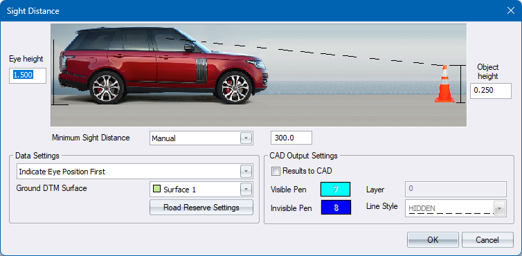
Sight Distance Type |
If Design Criteria Dialog is enabled, select the Sigh Distance Type to be used. The values for Eye height and offset, object height and offset as well as the minimum sight distance will be read from the Design Criteria. Alternatively, select “Manual” to specify custom values. |
|
Decision Complexity slider |
For the selection of the Minimum Decision Sight Distance, specify the complex of the decisions that the driver is expected to make, based on the minimum and maximum values specified in the Sight Distance tab of the Design Criteria Dialog. |
|
Adjust for vertical grade checkbox |
For the calculation of Stopping Sight Distance (SSD), check this option if you want to adjust the minimum SSD for vertical grade. The minimum sight distance will therefore vary along the road, based on the vertical grade.
|
|
Eye height |
Enter the driver's eye height above the road surface or ground DTM surface. |
|
Object height |
Enter the object's height above the road surface or ground DTM surface. |
|
Data Settings |
|
|
Indicate Eye Position First |
Select this option to indicate the eye position first. The rubberbanding will then be drawn to the object position. |
|
Indicate Object Position First |
Select this option to indicate the object position first. The rubberbanding will then be drawn to the eye position. |
|
Ground DTM Surface |
Specify the DTM surface that should be used in conjunction with the road strings model. |
|
Road Reserve Settings |
Click to display the road reserve settings dialog. |
|
CAD Output Settings |
|
|
Results to CAD |
Select this option to draw output to CAD. |
|
Visible Pen |
Specify the pen colour, for when the object is visible, for the CAD output. |
|
Invisible Pen |
Specify the pen colour, for when the object is invisible, for the CAD output. |
|
Layer |
Enter the CAD layer for the CAD output. |
|
Line Style |
Select the Line Style to be used fro CAD output. |