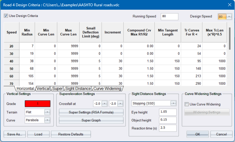
Entries in the design list are made for various design speeds. The default entries are extracted from TRH17.
General Settings
|
Option
|
Description |
|
Use Design Criteria |
Select this checkbox to use design criteria during the road design process. |
|
Design Speed |
Select the design to be used for the current road. |
|
Running Speed |
For the selected Design speed, specify an optional Running Speed. Running speed refers to the actual speed of a vehicle over a section of road. It is used for in the calculation of Minimum Stopping Sight Distance. |
|
Vertical Settings |
|
|
Grade Pen |
Click to select the pen colour in which grade envelopes should be drawn. |
|
Terrain Type |
Select the type of terrain through which the vertical alignment is being applied. |
|
Curve Type |
Specify whether the vertical curves must have a parabola or circular shape. This setting is stored in the roads file. Therefore, each road will have its own curve type setting. |
|
Superelevation Settings |
|
|
Crossfall at straights |
Enter the superelevation rate for straights for each side/carriageway. |
|
Super Settings |
Click to display the Super Settings. The label indicates which formula is being used, as specified in the Super Settings dialog. |
|
Super Graph |
Click to display the Superelevation rates graph. |
|
Save As button |
Click to save the settings to a *.vdc, design criteria file. |
|
Load button |
Click to load a *.vdc, design criteria file. You can load a file with the UK standards from our "Example" folder. |
|
Sight Distance Settings |
|
| Sight distance type list box | Select the sight distance type to edit |
| Eye height | Enter the eye height to be used for the selected sight distance type |
| Object height | Enter the object height to be used for the selected sight distance type |
| Reaction Time (s) | For Stopping Sight Distance: Enter the reaction time in seconds. This is the time it takes the driver to process information before acting. Reaction time is used in the calculation of Minimum Stopping Sight Distance. |
|
Curve Widening Settings |
|
| Use Curve Widening | Add automatic curve widening using design criteria. |
| Widening Settings | Click to display the Curve Widening Settings, where you can specify how the automatic curve widening is applied. |
|
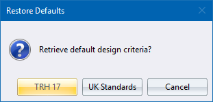
Restore Defaults button |
Click to restore the contents of the spreadsheets to the TRH or UK standards. The following dialog box displays.
confirmation message displays.
|
Horizontal Alignment
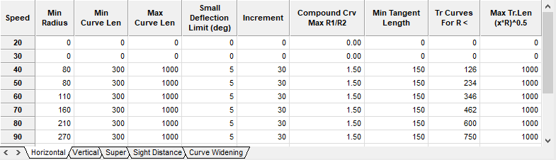
Each row in the spreadsheet represents a design speed, as indicated by the row headings.
|
Option
|
Description |
|
Speed |
The design speed increments can be altered by double-clicking in the appropriate row header. |
|
Min Radius |
Enter the minimum curve radius per design speed. |
|
Min Curve Len |
Enter the minimum radial curve length per design speed. |
|
Max Curve Len |
Enter the maximum radial curve length. |
|
Small Deflection Limit (deg) |
For deflection angles less than this value, the minimum length of the curve specified in the Min Curve Len column, will be increased by Increment for each 1 degree decrease in the deflection angle. |
|
Increment |
Enter the increment by which the minimum curve length will be increased, for each degree less than the Small Deflection Limit. |
|
Compound Crv Max R1/R2 |
Enter the maximum radius-ratio for compound curves. Flatter curve radius divided by the sharper curve radius. |
|
Min Tangent Length |
Enter the minimum tangent length for broken-back curves. Two successive curves will not be recognized as broken-back curves if the tangent is greater than 500 m. |
|
Tr Curves For R < |
Enter the radius that the program will use when deciding whether transition curves will be used or not. Transition curves will be used if the horizontal radii are less than these values. |
|
Max Tr. Len (X*R) ^0.5 |
Enter the value of X in this column (X*R)0.5. Transition curves lengths may not be greater than the values calculated by this formula. |
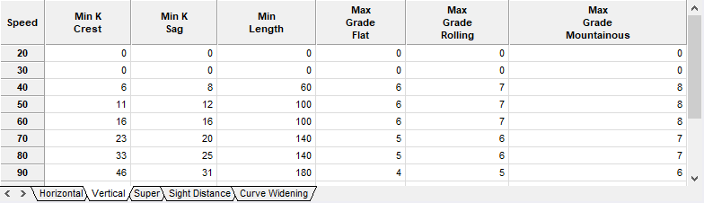
Vertical Alignment
|
Option
|
Description |
|
Min K Crest |
Enter the minimum K value for crest vertical curves at this design speed. |
|
Min K Sag |
Enter the minimum K value for sag vertical curves at this design speed. |
|
Min Len |
Enter the minimum length of any vertical curve at this design speed. |
|
Max Grade Flat |
Enter the maximum grade between VPI's in flat terrain at this design speed. |
|
Max Grade Rolling |
Enter the maximum grade between VPI's in rolling terrain at this design speed. |
|
Max Grade Mountainous |
Enter the maximum grade between VPI's in mountainous terrain at this design speed. |
Super Elevation
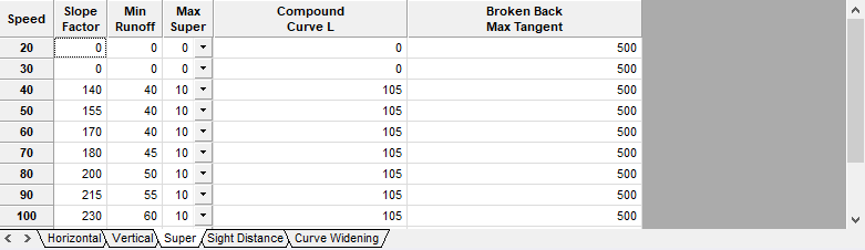
Each row in the spreadsheet represents a design speed as indicated by the row headings. The values in this spreadsheet will be used to when running Slave Super.
|
Option
|
Description |
|
Slope Factor |
Enter the relative slope factor for the relative design speed (s). |
|
Min Runoff |
Enter the length of superelevation run-off per design speed (L). |
|
Max Super |
Enter the maximum superelevation value. This is the largest superelevation value that will be used. |
|
Compound curve L |
If the length of the first circular curve (CT) of a compound curve pair is less than this value, Case 1 will be applied, otherwise Case 2 will be applied. These cases are explained in the design process. |
|
Broken Back Max Tangent |
Two consecutive curves with a common tangent of less than the value specified in this column, will be considered a broken-back curve. See design process. |
Sight Distance
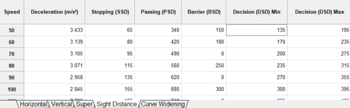
Each row in the spreadsheet represents a design speed as indicated by the row headings. The values in the spreadsheet can be used when running the Check Sight Distance, Sight Analysis and Pt-Pt Sight Dist functions.
|
Option
|
Description |
|
Deceleration (m/s2) |
Specify the deceleration rate per design speed for the calculation of Stopping Sight Distance(SSD). |
|
Stopping (SSD) |
Specifies the stopping sight distance per design speed. When running the various Sight Distance checking functions, you will also have the option to adjust these values for vertical grades along the road. |
|
Passing (PSD) |
Specifies the passing sight distance per design speed. |
|
Barrier (BSD) |
Specify the barrier sight distance per design speed. |
|
Decision (DSD) Min |
DSD is the distance required for a driver to detect an information source or hazard which is difficult to perceive in a roadway environment that might be visually cluttered, recognize the hazard or its threat potential, select appropriate action and complete the manoeuvre safely and efficiently.
|
|
Decision (DSD) Max |
DSD is the distance required for a driver to detect an information source or hazard which is difficult to perceive in a roadway environment that might be visually cluttered, recognize the hazard or its threat potential, select appropriate action and complete the manoeuvre safely and efficiently.
|
Curve Widening
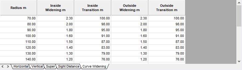
Each row in the spreadsheet represents the curve widening settings of the Curve Widening Table as indicated by the column headings. The values in this spreadsheet will be used when using curve widening and specifying the method as Widening Table.
|
Option
|
Description |
|
Radius m |
Specifies the radius of the curve to apply the automatic curve widening to. |
|
Inside Widening m |
Specifies the width to increase the inside of the curve by. |
|
Inside Transition |
Specifies the length of the transition to use on the inside of the curve. |
|
Outside Widening m |
Specifies the width to increase the outside of the curve by. |
|
Outside Transition |
Specifies the length of the transition to use on the outside of the curve. |
See Also Design Criteria and Curve Widening Settings