Pt-Pt Sight Dist
Perform sight distance checking between two user defined points.
|
Icon |
Command |
Shortcut Key |
Toolbar |
|
|
RD_POINTPOINTSIGHTCHECK |
|
|
This function allows you to do sight distance checking between two user defined points. This is useful for checking for stopping sight distance at intersections, for example.
 This function only works for Strings roads.
Procedure
- Select Alignment ► Pt-Pt Sight Dist to display the Sight Distance dialog.
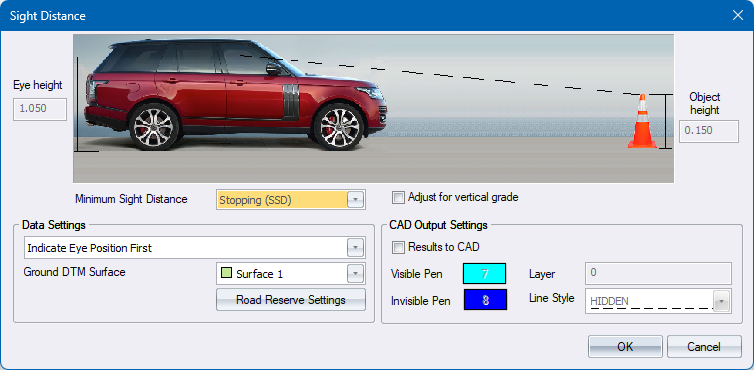
a. Select the appropriate Minimum Sight Distance type, if you have opted to use Design Criteria Dialog .
-
Click OK to continue.
-
If you are prompted to indicate the eye position for sight distance checking.
-
Graphically indicate the position of the driver's eyes. Civil Designer will automatically determine the height (z-coordinate) of the eye position and add the "eye height". If the indicated point is inside a road prism, the height will be interpolated from the road strings mesh. If the indicated point is outside all the road prisms, Civil Designer will interpolate the height from the specified ground DTM surface.
-
If the indicated eye position is inside a road prism, Civil Designer will also check the sight line against the road reserve of the road within which the eye position is located. So, if the sight line crosses the road reserve, it will indicate that the object is not visible. If the eye position is outside all the road prisms, the road reserves will be ignored.
-
If the road closest to the eye position has Design Criteria enabled, then the appropriate Design Speed and Minimum Sight Distance will be displayed in the Prompt area. The vertical grade at the eye position will also be calculated and displayed.
-

-
If you are prompted to indicate the object position for sight distance checking.
-
While moving the cursor (the object position), the sight distance will be displayed as text along the sight arrow.
-
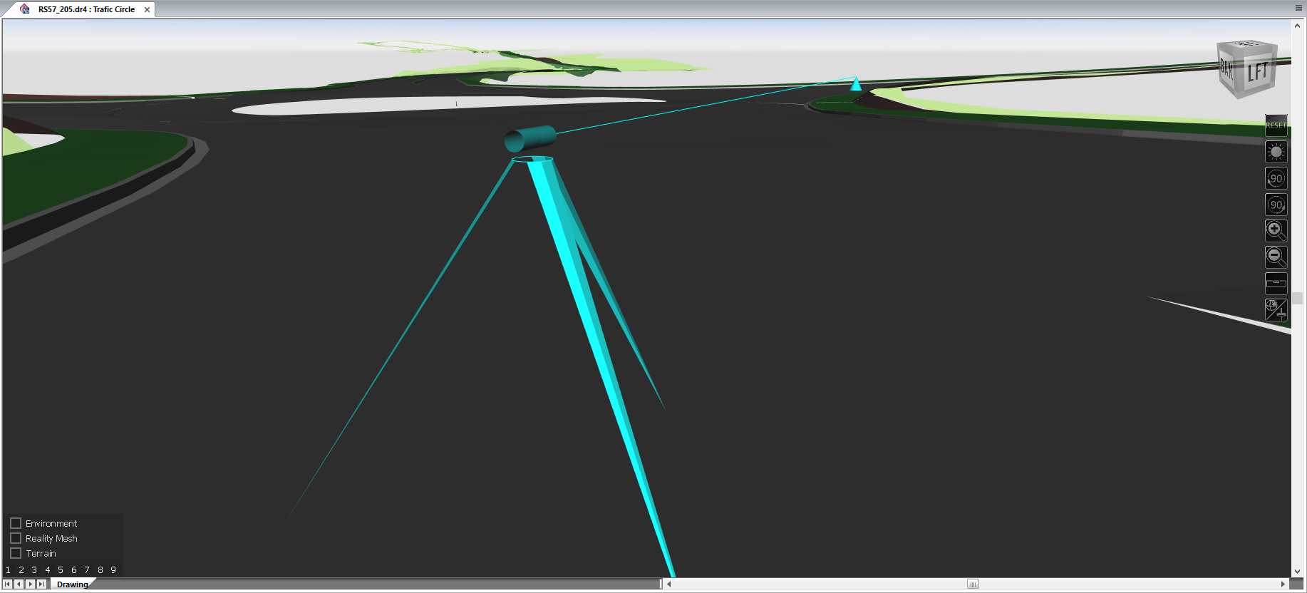
If the object can be seen from the eye position and the distance to the object is greater than the minimum sight distance, the sight arrow will be drawn in GREEN.
-
If the object cannot be seen from the eye position, or the distance for the object is less than the minimum sight distance, the sight arrow will be drawn in RED. If the object cannot be seen, because the sight line crosses the road reserve, "(H) will be displayed next to the distance.
- When you indicate the object position by clicking, the function will restart, prompting you from a new eye position. If you have selected the Results to CAD option, the results will be drawn in the specified CAD layer.
-
CAD Output
-
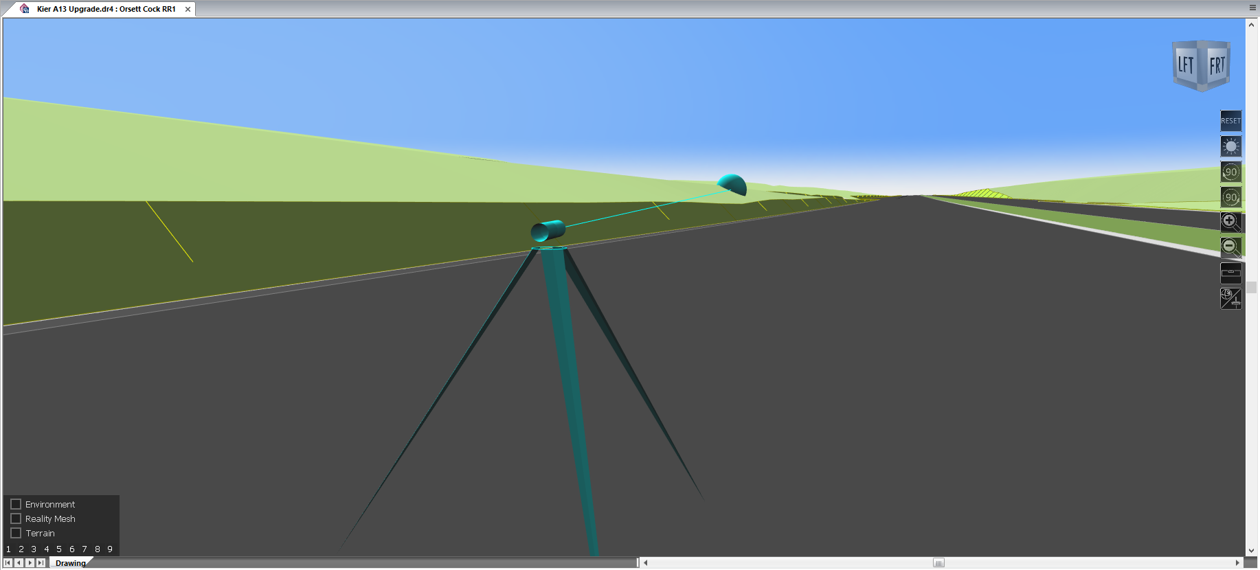
A 3D tripod will be drawn at the eye position.
-
A 3D pyramid will be drawn at the object position.
-
The Sight line will be drawn from the eye position to the object position in the specified Line Style.
-
If the object cannot be seen from the eye position, then:
-
A sphere will be drawn at the point where the sight line intersects the roads model or the DTM model.
- A 3D box will be drawn at the point where the sight line intersects the road reserve.
-