Validate Model
Validate the lines forming a model on a surface.
|
Icon |
Command |
Shortcut Key |
Toolbar |
|
|
TERRAINVALIDATEMODEL |
|
|
This function allows you to scan the line model on the visible portion of a selected surface to check for any errors. It does this by tracking a perimeter around the visible points, and then tracking all the polygons that form the surface within that perimeter. If an error in a polygon is encountered, a message indicates why the tracking failed. The view is then zoomed into the area where the failure occurred so you can correct the model.
There are a number of reasons why polygon tracking may fail causing the surface to be invalid. Among these are:
1. Duplicate points
2. Points that have only one line belonging to each
3. Lines that cross or are coincident with each other
4. Points that lie on another line but don’t break it
5. Crossing lines
Inspect the model carefully in the vicinity of the zoomed-in area and you will find the cause of the error.
 Only points within the current view are operated on.
Procedure
- The Model Validation options display.
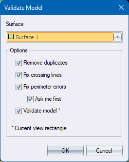
-
Fill in the relevant data and click OK to continue.
-
If Remove duplicates option was checked, then the surface is first scanned for duplicate points and removed if found. If any points are removed then the number of such points are listed to the Output Bar. Lines for the duplicate points are retained. See Remove Duplicates for more information on this function.
-
If Fix crossing lines option was checked, then the surface is first scanned for crossing lines and removed if found. If any lines are removed then the number of such lines are listed to the Output Bar.
- This function scans a DTM surface for lines that cross another line or that are partially or entirely collinear with another line. One of them will be deleted.
- The choice of which of the two lines is deleted depends of the following criteria:
- Lines that cross more than other lines are removed first.
- Longer lines are removed before shorter lines.
-
If Fix perimeter errors option was checked, then the perimeter of the surface is first scanned for errors and two types of errors are located.
- Connecting line not found is an error where a point on the perimeter has only one line belonging to it.
- Perimeter closes on itself is an error where the perimeter polygon is self-intersecting.
- If First show me option was checked then in each case the view is zoomed to show the problem line and a potential fix is suggested.
- Press Proceed to have the suggested fix applied, or press Stop to stop the operation allowing you to make more thoughtful changes yourself. Select the Don’t ask again option to not be prompted for subsequent errors of that type.
- If any automatic fixes were made then the number of such fixes are listed to the Output Bar
-
If Validate model option was checked then the site is scanned for polygon tracking errors.
-
Irrespective of whether any of these fix options are checked polygon tracking can still fail.
-
If polygon tracking fails, an error message is displayed.
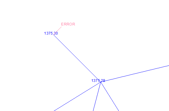
-
Click OK and the view zooms to the general area of the problem with a pink ERROR text pointing to the problem point. Using ID Point then is often helpful in identifying a problem that isn’t obvious.
-
Correct the problem and then re-run the function.
- Once the tracking has been completed, the following message displays.
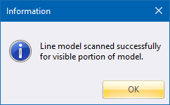
-
Click OK to close the message box.